Siemens S7-200 PC/PPI Cable Multi-Master Configuration
While modern Siemens lines like the S7-1200 and S7-1500 have transitioned almost entirely to PROFINET (Ethernet), the S7-200 relies on a specialized serial communication protocol. To program, monitor, or troubleshoot these machines, you need a specific piece of hardware: the PC/PPI Cable.
This guide provides a comprehensive deep-dive into what the PC/PPI cable is, how it functions, and how to navigate the challenges of using 1990s communication technology on modern computers.
What is the PC/PPI Cable?
The PC/PPI cable is a protocol converter designed to bridge the gap between a standard computer and the PPI (Point-to-Point Interface) port on an S7-200 CPU.
The Protocol Gap
The S7-200 uses a communication protocol based on RS-485 physics. However, most older computers provided RS-232 (serial) ports, and modern laptops provide USB. Because RS-485 is a multi-drop, differential signal and RS-232/USB are single-ended, you cannot simply use a "dumb" adapter. The PC/PPI cable contains active electronics to convert these signals and manage the timing of the PPI protocol.
Key Applications
- Uploading/Downloading: Moving logic from Siemens STEP 7-Micro/WIN software to the PLC.
- Status Monitoring: Viewing "Ladder Logic" in real-time to see which inputs are active and where a process is hung up.
- HMI Integration: Occasionally used to connect third-party touchscreens to the S7-200.
Evolution of the Hardware: Serial vs. USB
Depending on the age of your equipment and your laptop, you will encounter two main versions of this cable.
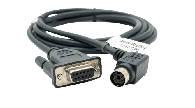
The RS-232/PPI Multi-Master Cable<
This is the classic version featuring a DB9 female connector on one end and a DB9 male on the other. It often includes a small box in the middle with DIP switches.
The DIP Switches:
These are used to manually set the baud rate (typically 9.6k, 19.2k, or 187.5k).
Legacy Requirement: This cable requires a native serial port or a very high-quality USB-to-Serial adapter.
The USB/PPI Multi-Master Cable
This is the modern standard. It eliminates the need for serial adapters by connecting directly to a USB port.
Drivers: Unlike the serial version, this requires specific Siemens drivers usually bundled with STEP 7-Micro/WIN.
Convenience: It draws power directly from the USB port and the PLC port, making it much more stable for field service.
Convenience: It draws power directly from the USB port and the PLC port, making it much more stable for field service.
Understanding the "Multi-Master" Capability
You will often see the term "Multi-Master" associated with these cables. This is a critical distinction in Siemens networking.
In a standard PPI network, only one device can "talk" at a time. If you have an HMI and a PLC talking, and you try to plug in your laptop to monitor the code, you have a second "Master" on the network. A Multi-Master PC/PPI cable is intelligent enough to negotiate its turn to speak on the network without causing a collision or a communication timeout.